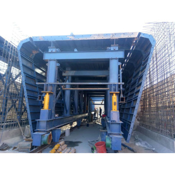


Lijian formwork is a specialized manufacturer which is engaged in construction formwork,steel structure and machinery. We can supply a series of quality products and services for construction company,such as formwork\steel structure technical consultation\project design\processing production\marketing\rental\on-site technical guidance and installation.
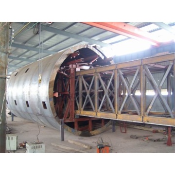
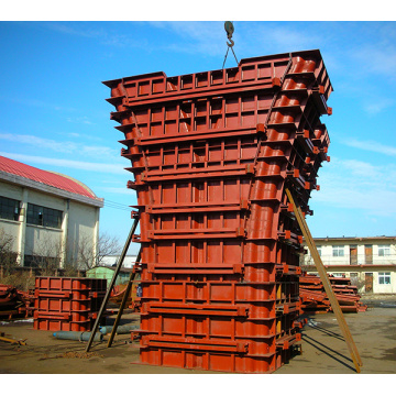
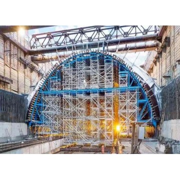
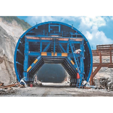
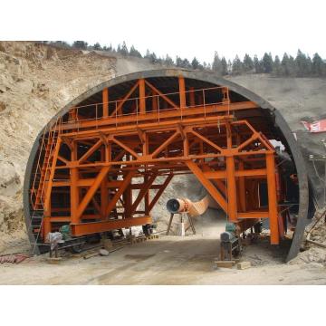
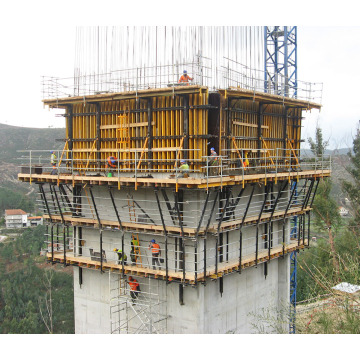
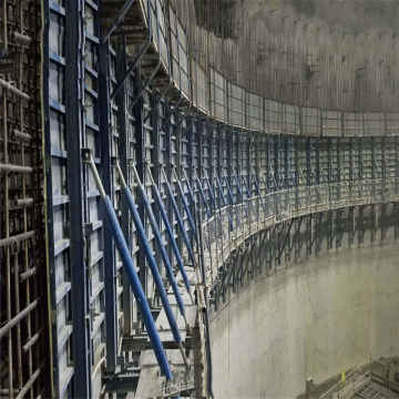
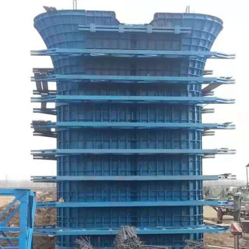
Our company has three branches including Beijing Lijian engineering technology co.,Ltd\Shandong Lijian formwork co,.Ltd\Anshan Lijian engineering co.,Ltd. Our company’s processing bases are located in Taian city,Shandong province and Anshan city,Liaoning province. Relying on advanced technologies and enormous processing capacity,the company’s business develop rapidly.Since company established,we had participated in hundreds of domestic major engineering construction. Our company’s product system widely use in infrastructure field,such as express rail\subway\water conservancy project\expressway\underground tunnel\municipal engineering,etc. And also has the features of reasonable structure,convenient operation,reliable quality and reasonable price,etc. We have already established good relationship with the construction enterprise,such as China Railway\China Railway Construction\China Hydropower\China Transportation construction\China Electric Construction,etc.
Our company’s business has already been expanded into 15 provinces and autonomous region in china and our products have exported to The United States,The United Arab Emirates,Cambodia,etc. When the company was established,we put quality and technology as our company’s principle. So we have already achieved the quality certification and applied for lots of national patents. Stability of products and advancement of technology are in the forefront of the industry.
”Reputation first,customers first” is enterprise purpose.”, ”Quality is survival,innovation promote development”is our business philosophy. Innovative technology and high-quality service let us win the trust of clients and create good economic benefits and social benefits.